

What web cams and IR cameras have in common
To see local warming and therefore weak points in our environment has been always been the most fascinating point within modern thermal imaging technology. Based on more efficient manufacturing technologies for the IR optical image sensors, those cameras resulted in a drastic improvement of their price-performance ratio. The devices got smaller, more robust and more economic in their power consumption. For some timenow measuring thermographic systems are available, which are – similar to a traditional webcam – controlled and powered only by an USB port.
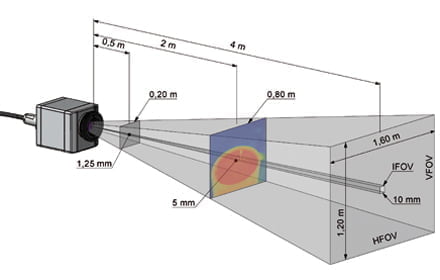
IR cameras are functioning like normal digital cameras: They have a sighting area, the so called field of view (FOV), which can typically vary between 6° for a telescopic optic and 48° for a wide angle optic. Most standard optics are showing a 23° FOV. The farther the object is away, the larger the observed area will be. But also the part of the image is increasing which is representing a single pixel. The good thing about it is that the radiation density is independent from the distance considering sufficient large measuring areas. Therefore, to a wide extend temperature measurements are not influenced by the distance to a measuring object. [1]
In the middle of the infrared range, the heat radiation can only be focused with optics made of germanium, germanium alloys, zinc salts or with surface mirrors. Those coated optics are still representing a significant cost factor in thermal imagers compared to the usual, in big volume manufactured optics for the visible light. They are designed as spherical three lens or as aspheric two lens arrangements. Especially for cameras with exchangeable optics each optic has to be calibrated for each single pixel in order to get correct measurements.
In almost all worldwide used thermographic systems, the heart of those cameras is a focal plane array (FPA), an integrated image sensor with sizes of 20.000 to 1 million pixels. Each pixel itself is a 17 x 17 μm2 to 35 x 35 μm2 bigmicro bolometer. Those 150 mm thick thermal detectors are heated up by the heat radiation within 10 ms to about a fifth of the temperature difference between object and chip temperature. This extremely high sensitivity is achieved by a very low thermal capacity in connection with a superb insulation to the silicon circuit and to the evacuated environment. The absorption of the semitransparent receiver area is improved by the interference of the transmitted and on the surface of the read out circuit reflected light wave with the succeeding
light wave. [2]
To use this effect of self interference, the bolometer area has to be positioned in about 2 μm distance from the readout circuit. Special etching techniques have to be used to structure the applied vanadium oxide or amorphous silicon materials. The specific detectivity of the described FPA’s is achieving values of 109 cm Hz1/2 / W. It is therefore one magnitude better than other thermal detectors which are for example used in pyrometers.
With the bolometer’s intrinsic temperature its resistance is changing. This change generates an electrical voltage signal. Fast 14 bit A/D converters are digitizing the amplified and serialized video signal. A digital signal processing is calculating a temperature value for each pixel. In real time it generates the known false color images. Thermal imaging cameras are requiring a relative extensive calibration in which a number of sensitivity values are allocated to each pixel at different chip and black body temperatures. To increase the measuring accuracy bolometer, FPA’s are often stabilized at defined chip temperatures with high control accuracy.
Due to the development of better performing, smaller and at the same time less expensive laptops, UMPCs, netbooks and tablet PCs it is nowadays possible to use their
- big displays for attractive thermal image presentations,
- optimized Li-Ion rechargeable batteries as power supply,
- computation capacity for a flexible and high value real time signal display,
- large memories for practically unlimited infrared video records and
- Ethernet, Bluetooth, WLAN and software interfaces for the integration of the thermographic system into their application environment.
The standardized and everywhere available USB 2.0 interface assures data transmission rates of
- 30 Hz with 320 x 340 pixel image resolution and
- 120 Hz with image sizes of 20.000 pixel.
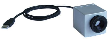
The 2009 introduced USB 3.0 technology is even suitable for XGA thermal image resolutions up to 100 Hz video frequency. In the area of thermography the use of the webcam principle enables totally new product features with a significant improved price-performance ratio. The infrared camera is connected via a 480 MegaBaud interface in real time with a Windows based computer which at the same time is supplying the required power.
The hardware of USB IR cameras
In the past, USB has been seen as a pure office communication medium. But opposite to FireWire, very broad use has initiated a number of developments to improve the industrial applicability and therefore the usability for a number of USB 2.0 end devices – especially of USB cameras. Those new product developments are:
- rugged up to 200°C usable USB cables with lengths of up to 10 m, applicable also in cable carriers [3]
- CAT5E (Ethernet) 100 m long cable extensions with signal amplifiers
- Optical fibre to USB modems for fibre cable lengths of up to 10 km [4]
Based on the high bandwidth of the USB bus, up to six 120 Hz IR cameras can be connected via a standard hub over a 100 m Ethernet cable to a laptop.
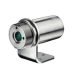
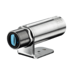
The water tight, vibration and shock resistant thermal imaging devices are NEMA 4 rated and therefore also suitable for demanding applications in test booths. The size of 45 x 45 x 62 cubic millimeter and the weight of 200 gram are reducing the effort for cooling housings and airpurges significantly.
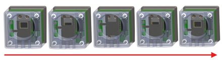
Due to the thermal drift of bolometer’s and their on chip signal processing, all worldwide marketed measuring IR cameras need an offset correction every few minutes. This correction is done by a motor driven motion of a blackened metal piece in the front of the image sensor. In this way, each image element is referenced with the same temperature. During those offset calibrations thermal imaging cameras are of course blind. In order to minimize this disturbing effect the offset correction can be initiated by an external control pin at a suitable point of time.
At the same time the cameras are designed to minimize the duration of their self calibration: Within the here discussed USB IR camera, the use of corresponding fast actors allows a self referencing within 250 ms. This is comparable with the duration of an eye lid motion and therefore acceptable for a lot of measurement processes. Inconveyor belt processes in which sudden hot spots have to be detected timely generated “good” reference image scan often be used as dynamic difference images. In this way a continuous mode is possible without a mechanically moved component.
Especially in applications where 10.6 μm-CO2-lasers are used an externally controlled closure of the optical channel is favorable in connection with an independent signalization of this self protected mode. Based on a good filter blocking all other typically in the spectral range between 800 nm and 2.6 μm working lasers are allowing temperature measurements during their operation.
Main application areas of the described thermal imaging device are:
- the analysis of dynamic thermal processes during the product and process development,
- the stationary use for a continuous monitoring and control of heating and cooling procedures and
- the occasional use in the electrical and mechanical maintenance and for the detection of heat leakages in buildings.
For the application in the R&D area the possibility of a 120 Hz video recording is very advantageous. Thermal processes only shown in the camera’s field of view for a short time can be analyzed in slow motion. Afterwards, single images can be generated in full geometric and thermal resolution out of such a video sequence. In addition, exchangeable optics including a microscope accessory are offering a lot of possibilities to adapt the camera to different measuring tasks. While 9° optics are rather suitable to monitors details from a greater distance, a microscope accessory can be used to measure objects of 5.5 x 4.2mm2 size with a geometric resolution of 35 x 35 μm2.
For the online use of USB IR cameras an optically isolated process interface is advantageous. The temperature information generated out of the thermal image can be supplied as a voltage signal. In addition, area reference demissivities and contact or non contact measured reference temperatures can be transmitted via a voltage input to the camera system. For documentation purposes an additional digital input can initialize snapshots and video sequences. Those thermal images can be stored automatically on central servers. Documenting each single piece of a production lot temperature and especially uniformity information can be monitored from different computers within a network.
Thermal analysis software guaranties flexibility
There is no driver installation needed because USB IR cameras are using the already in Windows XP and higher integrated standard USB video class and HID driver. The single pixel related real time correction of the video data and the temperature calculation are done on PC. A for only 20.000 sensor pixels impressive image quality is achieved by a complex software based rendering algorithm which is calculating temperature arrays in VGA format. The application software is characterized by a high flexibility and portability. Besides the functions which are standard for a thermographic software, there are advanced features like:
- mixed scalable color pallets with isotherms,
- many data and thermal image export functions to support reports and offline analyses,
- horizontal and vertical line displays,
- unlimited number of measuring areas with separate alarm options,
- difference video displays based on reference images,
- temperature/ time diagrams for different regions of interest.
Furthermore, the software offers a layout mode which saves different display adjustments. An integrated video software enables the editing of radiometric AVI files. Such files can also be analyzed offline based on the multiple inparallel usable software. The video acquisition modes are also allowing the intermittent recording of slow thermal processes and their fast display.
The transfer of real time data to other programs is doneby a comprehensive documented DLL as a part of a software development kit. Via this DLL interface all other camera functions are also controllable. Alternatively the software can communicate with a serial port. Using this data link, RS422 adapters can be connected directly.
Application examples
In the next chapter three typical applications are discussed. They are representing examples out of a wide field of camera usage.
Optimizing production processes
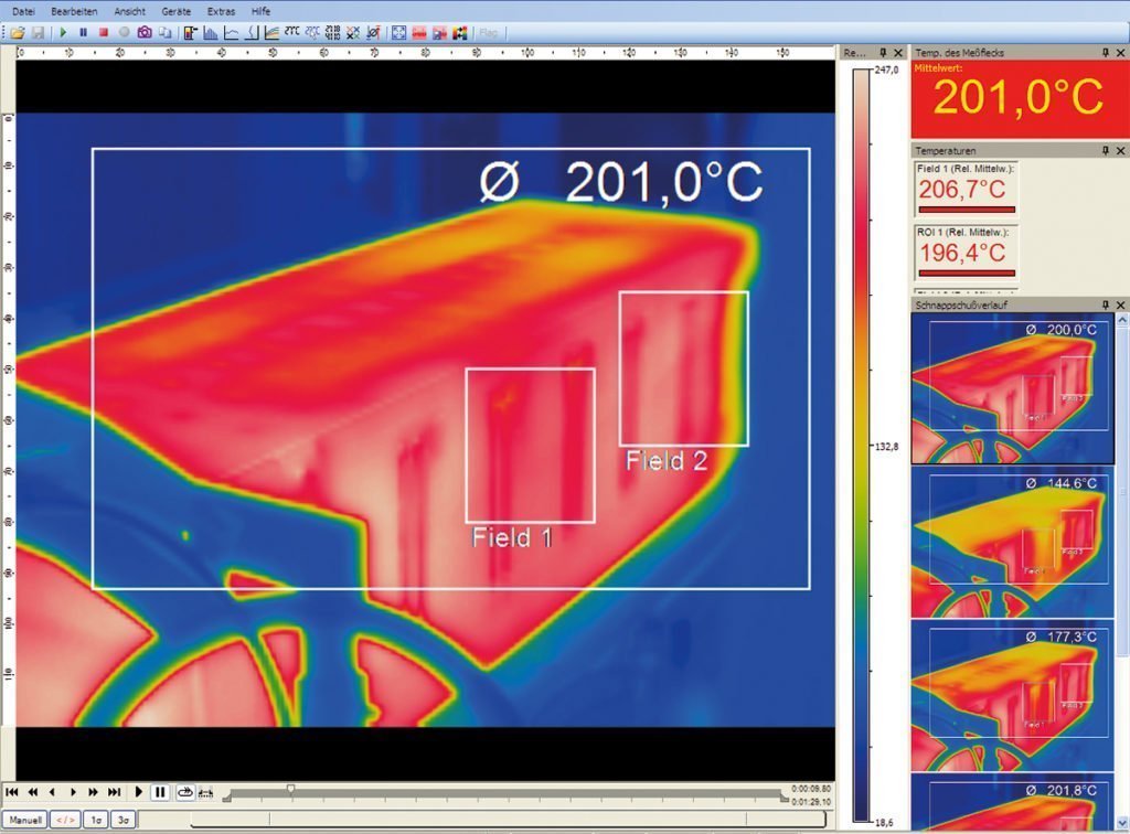
The production of plastic parts, like PET bottles, requires a defined heat up of the so called preforms in order to guaranty a homogeneous material thickness during the blow molding. Test runs are done with only a few of the 20 mm thick blanks with full working speed of about 1 m/s. In order to measure the temperature profile of a preform a video sequence with 120 Hz has to be recorded because the moment can vary where those blanks are in the field of view. The camera is positioned in such a way that it follows the motion of the material under an oblique angle – similar to the view to the last wagon of a running train. Finally, the IR video sequence delivers the right temperature profile which is important for the adjustment of all heating parameters.
Line scanning in glass toughening lines
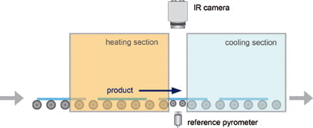
After construction glasses had been cut to their final form quite often, they have to be toughened on their surface. This is done in glass toughening furnaces in which the cut glasses are heated up to about 600°C. After the heatup movable rolls are transporting the material from the oven into a cooling section. Here the surface is cooled down quickly with the same speed. In this way a fine crystalline hardened structure is generated which is especially important for safety glasses. The fine structure and especially the braking strength of the glass depends on a uniform heating and cooling pattern for all partial areas of the glass material.
Because oven housing and cooling section are located close to each other it is only possible to monitor the oven leaving glass surfaces through a small slot. As a result in the infrared image the material is shown only in a few lines. The software displays the glass surface as an image generated out of lines or line groups. Those lines are taken out of every 8 ms recorded thermal images. The camera is measuring the slot in a diagonal mode allowing, with a 48° optic, an overall field of view of 60°. Glass has different emissivities depending on its coating layers. An IR thermometer is measuring the exact temperature on the non coated lower side at the for those surfaces optimal wavelength of 5 μm. As the result a corrected emissivity is calculated for the overall measuring image. Finally, those measuring images are allowing an exact adjustment of all heating sections in the oven assuring a good thermal homogeneity.
Conclusions
The new IR imaging technology represents a novelty with respect to flexibility and width of its possible applications. Besides of sophisticated temperature analysis when connected to tablet PCs the device can also be used to solve simple maintenance tasks. With the exception of the hardware of the USB IR camera measuring heads itself both significant other components of the described thermographic system – Windows software and PC hardware – can also be actualized later. This is done on the one hand side by simple downloads of software updates and extensions. And on the other hand side due to the standard USB interface the measuring system can be supplemented with technologically and functionally further developed PC hardware at any time.
References
- VDI/VDE Richtlinie, Technische Temperaturmessungen – Spezifikation von Strahlungsthermometern, Juni 2001, VDI 3511 Blatt 4.1
- Trouilleau, C. et al.: High-performance uncooled amorphous silicon TEC less XGA IRFPA with 17 μm pixel-pitch; “Infrared technologies and applications XXXV”, Proc. SPIE 7298, 2009
- Schmidgall, T.; Glänzend gelöst – Fehlerdetektion an spiegelnden Oberflächen mit USB 2.0 – Industriekameras, A&D Kompendium 2007/2008, S. 219
- Icron Technology Corp.; Options for Extending USB, White Paper, Burnaby; Canada, 2009
